Posts

MVA Remote Vibration Analysis Services

Image
Introduction I am providing this cost-effective unique Vibration Analysis Service due to an injury from a motor vehicle accident and now need to work from home. Robert has 24 years of experience as a Vibration Analyst in the Mining, Timber and Food industries. He is the owner of Midwest Vibration Analysers   Robert has held roles as Maintenance Supervisor, Plant Inspector (Oil & gas) Predictive Systems Analyst, Maintenance Training coordinator, Reliability Supervisor, Reliability Superintendent, and Condition Monitoring Technical Specialist Please check Roberts's Linkedin Profile for recommendations and endorsements: https://www.linkedin.com/in/robert-smith-4a43a869/   W hy Vibration Analysis? Every factory or process plant has rotating machinery like pumps, motors, gearboxes other types of process equipment. All these types of equipment incorporate shafts, couplings and bearings. As bearings and couplings wear, shafts go out of alignment and structural looseness occurs and vib

Autocorrelation Instructions for AMS Machinery Manager Version 5.5 or higher. Simply explained

Image
Autocorrelation Instructions for AMS Machinery Manager Version 5.5 or higher. Images from Emerson for demonstration purposes In this above example, we have two Acceleration Time Wave Forms (TWF) from two different machines. The first or top TWF is from a Blower inboard bearing in the vertical plane. The second is a cooling water centrifugal pump inboard bearing in the vertical plane. Notice in both TWF’s it is hard to detect if there is any repetitive impacting To Auto correlate, select the time waveform. In the above example, we click on the first TWF blower. Once selected then right-click – (see below Autocorrelation,) After the right-click the above menu box will appear. (Select Auto correlate. See results below) In this example for the blower, the autocorrelation is near 1 so the impacts are repetitive and is most likely related to a bearing defect. The second example below is a centrifugal cooling pump. Again, once the TWF is selected we again right-click and select autocorrel

Vibration Analysis of a Bent Shaft.

Image
 Vibration Analysis of a Bent Shaft. A bent shaft predominantly causes high 1X axial vibration. The dominant vibration is normally at 1X if the bend is near the centre of the shaft, however, you will see 2X vibration if the bend is closer to the coupling. The axial measurement is the key indicator. Spectrum : Look for a high 1X peak in the axial plane.  If the bend is close to the coupling then you will see a higher 2X peak.  You may also observe higher than-normal 1X and 2X peaks in the radial direction. The phase is also a good indicator to diagnose a bent shaft. The phase at 1X measured in the axial directions at opposite ends of the component will be 180° out of phase. Please note if measurements are taken at the face of the component they will be in phase. TimeWave Form : The TWF is not a good indicator, however, a sinusoidal waveform is expected in the axial plane. Bent Shaft Spectrum in the axial direction. Please note the 2Xrpm will tend to appear if the shaft bend is closer t

Vibration data for Shaft Misalignment - Angular and Offset

Image
  Vibration Data for Shaft  Misalignment  Offset/Parallel Misalignment 1X,2X,3X & sometimes 4X & 5X in the radial direction at Motor Running Speed, RPM Angular Misalignment: 1X & 2XRPM in the axial direction. 1X,2X & sometimes 3X in the radial direction. This can depend on the type of coupling in service. Offset/Parallel Misalignment The Centerlines are parallel but offset.  Offset Misalignment Spectrum. Be aware 3X & 4X RPM also be present. Note the 180 deg out of phase across the Coupling This is why phase measurements are needed to help confirm parallel misalignment. The 2X RPM is usually higher than 1X RPM. Readings taken radially in the horizontal and vertical planes should be similar. Angular Misalignment Spectrum :  Basically stated, angularity is the gap difference across two coupling faces-normally top to bottom or side to side. Angular misalignment in the radial direction Spectrum: Angular misalignment produces a bending moment on each shaft, and this g

Commtest – Ascent Software Vibration Data Analyzed.

Image
  Commtest – Ascent Software Vibration Data Analyzed. If you are using a Commtest Vibration Analyzer and Ascent Software and require assistance or a second opinion on the analysis I am available to assist. Data can be sent to me via email. A fully written report will be presented to ISO 10816-7:2009 I provide expert vibration analysis and machinery diagnostics for Mining and other Industries. I have been a Vibration, Analyst for over 24 years and over 40 years in industrial maintenance with a proven track record. Robert is qualified for VA Level 111 and is a Condition Monitoring Technical Specialist. Robert has held roles as Maintenance Supervisor, Plant Inspector (Oil & gas) Predictive Systems Analyst, Reliability Supervisor, and Reliability Superintendent. Please contact if interested Contacts Email: robbieccs@gmail.com Alternative email: robertmva@yahoo.com.au

PERSONAL CASE HISTORY –CRACKED FAN/BLOWER IMPELLER

Image
  PERSONAL CASE HISTORY – CRACKED FAN/BLOWER IMPELLER In the early years as a Vibration Analyst (2000) I was working at a processing plant in Bathurst NSW. This fluid bed dryer had a fan/ blower around 130Kw, 2 pole motor 2850 RPM. This was located in a fan room with 7 other fans/ blowers. The vibration at the plumber block bearings were starting to rise and at 10mm/sec RMS and there was a concern. So dynamic balancing was scheduled. There was only access to the fan impeller through a small side hatch. The fan could not be fully isolated from other fans so you had moist hot air coming through, which made it hard to see and work. It was impossible to inspect and assess the impeller condition. The inlet ducting could not be removed easily as it was welded which was a poor design. The balancing, instrument was IRD but I also made calculations with polar plots and vectors but the unbalance could not be improved. The vibration amplitude climbed to 15mm/sec RMS over the next week and

When the curiosity of a Vibration Issue Pays Off

Image
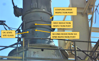
  When the curiosity of a Vibration Issue Pays Off Case History by Robert Smith    Primary Regrind Mill Broken Gear   Introduction   I had only been in my Reliability Superintendents role for a few months and I was in the process of setting up a Vibration Analysis Program. This involves looking at all plant locations and the critical of equipment.   As I was inspecting the exterior of this vertical mill gearbox I could hear what I would describe as a clicking sound. The sound did not sound like a high-energy impact but I was curious. I asked a maintenance person working in the area who explained the clicking noise had been there for a while and they did not think it was an issue. The vibration database was not set up at this time for this area of the plant.   To get a reasonable idea of the frequency of the impacts I used a stopwatch. I would count 50 low energy impacts and stop the timing. The timing would vary and remember I was only doing this for basic informati